GPU Mesh Voxelizer Part 1
bronson
- posted on
- No Comment
In this article, we’ll start porting my naive mesh voxelizer to a multithreaded mesh voxelizer that runs on the GPU through Compute Shaders. First, we’ll set up the compute shader to position all the voxel grid points. Then, we’ll draw the grid points directly from the Compute Buffer on the GPU. From there, we’ll discuss how we can use the Separating Axis Theorem (SAT) to test for collisions between voxels and triangles.
Setting up the Compute Shader
If you’re new to compute shaders, I recommend you start by reading my earlier tutorial on the subject because I’m about to gloss over the basics. So what do we need to position the voxel grid? If you followed my previous Voxelization article, you might already know, but I’ll go over it anyway. First, we need the minimum point of the mesh’s bounds, which is the bottom-left-front point. It’s the minimum point because it’s the point where the X, Y and Z values are at their minimum. Given this point and our desired voxel size, we can lay down our voxel grid. We also need the Width, Height and Depth of the mesh’s bounds in voxel units. In other words, how many voxels can we fit in X, Y and Z dimensions? Let’s start writing the compute shader.
#pragma kernel VoxelizeMesh
RWStructuredBuffer<float4> _VoxelGridPoints;

float4 _BoundsMin;
float _CellHalfSize;
int _GridWidth;
int _GridHeight;
int _GridDepth;

numthreads(1,1,1)]
void VoxelizeMesh(uint3 id : SV_DispatchThreadID)
{
    float cellSize = _CellHalfSize * 2.0;

    _VoxelGridPoints[id.x + _GridWidth * (id.y + _GridHeight * id.z)] = float4(
        _BoundsMin.x + id.x * cellSize,
        _BoundsMin.y + id.y * cellSize,
        _BoundsMin.z + id.z * cellSize, 1.0);
}
There’s not much going on here yet. We convert the thread id from three-dimensional to a one-dimensional index and then calculate the current voxel position. If you haven’t guessed already, we’ll run a single thread per voxel. This way, the thread id corresponds to the x,y,z position of a voxel in voxel-space, and we convert it to local-space. Then, we take the converted value and store it in our buffer of points. By the way, you may be wondering why we pass the cell half-size if we’re only using the full size. The half-size will come in handy later when we need to calculate the center of each voxel. Next, we’ll write a custom shader to draw directly from our buffer of points.
Drawing from a Compute Buffer
To draw from the compute buffer, we first convert each point from local-space (its position relative to the mesh’s origin) to world-space (its position relative to the world’s origin) and then draw. We do this by multiplying the point’s position by the Local-to-World matrix of the mesh. Since we’re not drawing these points via the regular render pipeline, we’ll have to supply this matrix to the shader. We’ll also point the shader to the compute buffer that holds our array of points. Here’s what the vertex shader looks like:
struct v2f
{
    float4 position : SV_POSITION;
    float4 color : COLOR;
    float size : PSIZE;
};

float4x4 _LocalToWorldMatrix;
StructuredBuffer<float4> _VoxelGridPoints;
float4 _Color;

v2f vert(uint vertex_id : SV_VertexID, uint instance_id : SV_InstanceID)
{
    v2f o;
    float4 localPos = _VoxelGridPoints[instance_id];
    o.position = UnityWorldToClipPos(mul(_LocalToWorldMatrix, localPos));
    o.size = 5;
    o.color = _Color;
    return o;
}
And, as for the fragment shader, we have this:
float4 frag(v2f i) : COLOR
{
    return i.color;
}
By the way, I skipped the Shaderlab boilerplate, but I linked the finished project further down. You can see the complete file there.
Next, we need to pass the data to the material and ask it to draw. For simplicity, I use DrawProceduralNow in the OnRenderObject callback. I’m not sure if this callback works in URP or HDRP, but we’ll switch to a more robust API that will work in the future. By the way, the OnRenderObject method gets called on all MonoBehaviours just after they render. So we’ll add this to our VoxelizedMesh component:
void OnRenderObject()
{
    VoxelizeMeshWithGPU();

    _gridPointMaterial.SetMatrix("_LocalToWorldMatrix", transform.localToWorldMatrix);
    _gridPointMaterial.SetVector("_BoundsMin", new Vector4(_boundsMin.x, _boundsMin.y, _boundsMin.z, 0.0f));
    _gridPointMaterial.SetBuffer("_VoxelGridPoints", _voxelPointsBuffer);
    _gridPointMaterial.SetPass(0);
    Graphics.DrawProceduralNow(MeshTopology.Points, 1, _gridPointCount);
}
In this case, the _gridPointMaterial is a material that uses our custom Shader. We pass all the data to the material, set the pass to our first (and only) pass, and call DrawProceduralNow. As for the DrawProceduralNow arguments, we specify the mesh topology, number of vertices per mesh, and how many meshes to draw. In our case, we’re drawing points, each point has a single vertex, and finally, the number of points in the _voxelPointsBuffer. To finish, we’ll look at the VoxelizeMeshWithGPU function, which initializes the data.
So let’s recap what we need. For the compute shader, we need the bounds’ min position in local-space, the half-size of a voxel cell and the grid’s width, height and depth. For the material, we need the local-to-world matrix and the bounds’ min position in local space. Of course, we also need to create a compute buffer that’ll hold the position of all the grid points. I’ll drop the entire function here. It’s primarily boilerplate. If any of it is unfamiliar, you may need to revisit this article to learn about compute shaders or this other article to understand the simple voxelizer that this code is based on.
void VoxelizeMeshWithGPU()
{
Bounds bounds = _meshCollider.bounds;
_boundsMin = transform.InverseTransformPoint(bounds.min);
Vector3 voxelCount = bounds.extents / _halfSize;
int xGridSize = Mathf.CeilToInt(voxelCount.x);
int yGridSize = Mathf.CeilToInt(voxelCount.y);
int zGridSize = Mathf.CeilToInt(voxelCount.z);
_voxelPointsBuffer?.Dispose();
_voxelPointsBuffer = new ComputeBuffer(xGridSize * yGridSize * zGridSize, 4 * sizeof(float));
if (_gridPoints == null || _gridPoints.Length != xGridSize * yGridSize * zGridSize)
{
_gridPoints = new Vector4[xGridSize * yGridSize * zGridSize];
}
_voxelPointsBuffer.SetData(_gridPoints);
var voxelizeKernel = _voxelizeComputeShader.FindKernel("VoxelizeMesh");
_voxelizeComputeShader.SetInt("_GridWidth", xGridSize);
_voxelizeComputeShader.SetInt("_GridHeight", yGridSize);
_voxelizeComputeShader.SetInt("_GridDepth", zGridSize);
_voxelizeComputeShader.SetFloat("_CellHalfSize", _halfSize);
_voxelizeComputeShader.SetBuffer(voxelizeKernel, VoxelGridPoints, _voxelPointsBuffer);
_voxelizeComputeShader.SetVector("_BoundsMin", _boundsMin);
_voxelizeComputeShader.GetKernelThreadGroupSizes(voxelizeKernel,
out uint xGroupSize,
out uint yGroupSize,
out uint zGroupSize);
_voxelizeComputeShader.Dispatch(voxelizeKernel,
Mathf.CeilToInt(xGridSize / (float) xGroupSize),
Mathf.CeilToInt(yGridSize / (float) yGroupSize),
Mathf.CeilToInt(zGridSize / (float) zGroupSize));
_gridPointCount = _voxelPointsBuffer.count;
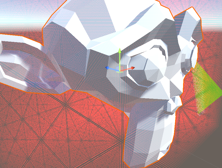
}So at this point, we have a compute shader that runs on every voxel surrounding a mesh, and we’re able to draw the voxel grid, which will come in handy for debugging later. On my machine, I can draw around a million points before the framerate drops in the editor.
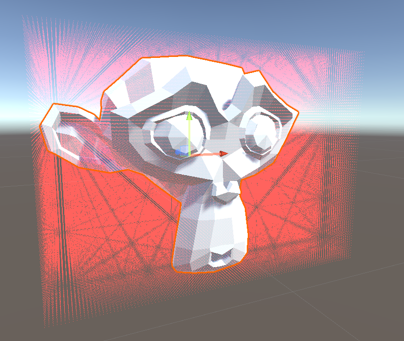
This is significantly better than our naive voxelizer, where drawing using OnSceneGUI and the Handles API had a notable impact on performance. Additionally, now that we wrote the boilerplate, we only have to implement voxel/triangle collisions in the compute shader, and our voxelizer is nearly complete. We’ll do that using the Separating Axis Theorem.
Separating Axis Theorem
I’ll briefly explain the separating axis theorem and provide links to some other resources later. The separating axis theorem is a technique for detecting collisions between two convex objects. The idea is that if we look at two convex objects from a handful of specific angles, if there’s an angle in which the two objects don’t overlap, then they aren’t colliding. In other words, imagine you couldn’t see depth. If you held two things, one in front of the other, it would appear as these two objects overlap from some angles. However, if you can find an angle where they aren’t, you know they aren’t colliding. That’s essentially how the SAT algorithm works.
I won’t implement SAT yet because it would make this post too long, but I’ll share some resources where you can read more about it if you’d like to take a crack at it. Otherwise, stay tuned for part 2.
Check out the project on Github to see it in action. If you’d like to learn more about SAT, I found this article very helpful. You can also read the wikipedia page here. If you appreciate this article, join my mailing list, and I’ll email you when part 2 is released.