Generate a Maze using Compute Shaders in Unity
bronson
- posted on
- No Comment
This article covers the basics of Compute Shaders. We’ll generate a simple maze using a basic Compute Shader and the binary tree maze algorithm. This relatively simple explanation of Compute Shaders will serve us for more complex examples in future articles.
Compute Shaders
There are plenty of other tutorials covering Compute Shaders, so I’ll try to be brief and direct. Compute Shaders are a way to offload work from the CPU to the GPU. Offloading work is good for two reasons: first, while the CPU is busy computing everything that changed in a given frame, the GPU is usually just waiting to be given things to render. Second, the GPU is exceptionally well suited to running tons of parallel computations. The drawback is that not all algorithms are designed to run in parallel. As a result, you may need to rethink your algorithm’s design or how you prepare your data.
And so, the reason you would consider using Compute Shaders is to squeeze more performance out of your application. That speed comes from taking advantage of the highly parallelized nature of the GPU. You can sometimes gain performance by avoiding the need to pass information between the CPU and GPU. However, that’s not the case for us right now.
So, let’s create a new Compute Shader and get started!
A New Compute Shader
A brand new Compute Shader created from Unity’s Compute Shader template looks like this:
#pragma kernel CSMain

RWTexture2D<float4> Result;

[numthreads(8,8,1)]
void CSMain (uint3 id : SV_DispatchThreadID)
{
    Result[id.xy] = float4(id.x & id.y, (id.x & 15)/15.0, (id.y & 15)/15.0, 0.0);
}
By the way, I removed the default comments for simplicity. There are four components here: the kernel declaration, the Result variable, the numthreads attribute, and the CSMain function. So let’s go over each one.
In this context, kernels are essentially functions that C# components can execute. The line #pragma kernel CSMain declares a kernel called CSMain, where CSMain is the function’s name. A compute shader can have multiple kernels. In this case, you declare each one with a similar #pragma kernel [function name] line. Later I’ll show you how to retrieve and run different kernels in C#.
Next is the Result variable. It’s of type RWTexture2D. That means it’s a texture that we can read from and write to, where each pixel of the texture is a float4. By default, this isn’t pointing to anything, so we’ll link this variable to a RenderTexture from a C# script later.
The numthreads attribute is a bit more complicated. It indicates the size of the threadgroup the GPU will use to run our compute shader. For example, ours is (8, 8, 1), which means the GPU will wait for 64 threads to be free (8x8x1 is 64) and then assign each of those threads a three-dimensional GroupThreadId and DispatchThreadId. The group id will go from (0, 0, 0) to (8, 8, 1). From a C# script, we’ll tell the compute shader how many groups (of 8x8x1 threads) to dispatch. So if we dispatch 10x10x1 threads, the DispatchThreadId will go from (0, 0, 0) to (8×10, 8×10, 1×1). Let’s assume each thread will work on a single pixel of an image. If the image is 8×8, we only need a single group for each thread to cover each pixel because our group is also 8×8. If the image is 16×16, we need two groups in X and two groups in Y, so four groups cover each pixel. If you’re struggling to understand this, I suggest you move on and come back when you have a sharper understanding of the context surrounding compute shaders.
Finally, there’s the CSMain function. Ultimately, this function is just writing some colours into the Result texture. The default draws a neat fractal, but that’s not important. What’s important is this line:
Result[id.xy] = float4(id.x & id.y, (id.x & 15)/15.0, (id.y & 15)/15.0, 0.0);That line sets the R, G, B, A channels of the Result texture at a given coordinate. With that, we’ve covered that’s the entire compute shader, but how do we use it? Let’s write a simple C# script to run and display our compute shader.
Compute Shader Runner
To run our compute shader, we need two things: a reference to it and a RenderTexture to which it will draw. Then, to display it, we’ll attach our script to a camera and use the OnRenderImage callback to draw to the screen. Here’s the entire script:
public class TemplateComputeShaderRunner : MonoBehaviour
{
    [SerializeField] ComputeShader _computeShader;
    [SerializeField] int _size;

    RenderTexture _renderTexture;

    void Start()
    {
        _renderTexture = new RenderTexture(_size, _size, 24);
        _renderTexture.filterMode = FilterMode.Point;
        _renderTexture.enableRandomWrite = true;
        _renderTexture.Create();

        _computeShader.SetFloat("_Resolution", _renderTexture.width);
        var main = _computeShader.FindKernel("CSMain");
        _computeShader.SetTexture(main, "Result", _renderTexture);
        _computeShader.GetKernelThreadGroupSizes(main, out uint xGroupSize, out uint yGroupSize, out uint zGroupSize);
        _computeShader.Dispatch(main, _renderTexture.width / (int) xGroupSize, _renderTexture.height / (int) yGroupSize,
            1);
    }

    void OnRenderImage(RenderTexture src, RenderTexture dest)
    {
        Graphics.Blit(_renderTexture, dest);
    }
}
It’s straightforward:
- We create a new square
RenderTexture. Addtionally, to allow the compute shader to write to it, we always enable random write. - We retrieve the id of the
CSMainkernel. Set theResultvariable of our compute shader to theRenderTexturewe just created. Remember when I said we would link our Result variable to a RenderTexture from C#? - Get the thread group sizes. These are the values defined in the
numthreadsattribute. Ours were (8, 8, 1) if you recall. - Dispatch the compute shader.
When we dispatch a compute shader, we specify which kernel to run and how many thread groups of each kind to create. In our case, we’ll run one thread per pixel. To do this, we take the resolution of the image divided by the size of a group. For example, if our image is 16×16 and our groups are 8×8, we need two groups in X and two groups in Y to cover the whole image. If you attach this script to a camera in an empty scene and link the values in the Inspector, you’ll see the result of running our compute shader. This works because the OnRenderImage callback draws our RenderTexture onto the camera’s target, which is the screen. It’s worth mentioning that OnRenderImage only works in the built-in render pipeline, so avoid using URP or HDRP.
Now let’s move on to generating a maze.
Binary Tree Maze Algorithm
We’ll use the binary tree maze generation algorithm. This algorithm is the simplest maze generator I know. The mazes that it generates aren’t my favourite, but we’re striving for simplicity over beauty right now. The algorithm goes like this:
- First, construct all the walls of the maze in a grid pattern.
- Then, for each maze tile, flip a coin. If the coin comes back heads, carve a path to the north, otherwise carve a path to the east.
- If you’re on the eastern border, you can only go north, and if you’re on the northern border, you can only go east, so there’s no need to flip.
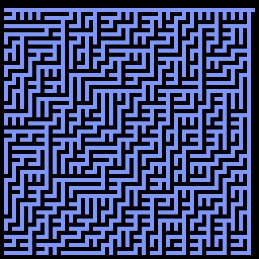
The unfortunate consequence of this otherwise simple and elegant algorithm is that the maze’s northern and eastern borders will always look the same. Now let’s implement this in a compute shader. Here’s an example:
Binary Tree Maze Implementation
We’ll use two passes to generate the maze, one to place all the walls and then a second to carve out passages. The reason is that since our shader runs both in parallel and in an arbitrary order, we may carve out a path only to have a wall placed on top of it later. Starting from our basic compute shader, add a new kernel called Prepass:
#pragma kernel Prepass
[numthreads(8,8,1)]
void Prepass(uint3 id : SV_DispatchThreadID)
{
if (id.x == 0 || id.y == 0 || id.x == _Resolution - 1 || id.y == _Resolution - 1)
{
Result[id.xy] = _WallColor;
}
else if (id.x % 2 == 0 || id.y % 2 == 0)
{
Result[id.xy] = _WallColor;
}
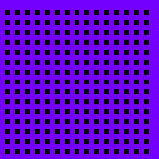
}First, we check if we’re on the edge of the image and place a wall. Doing so draws a border around our maze. Then, we place a wall on every even-numbered pixel. As a result, we have a grid of walls with holes for tiles. Here’s what the prepass looks like with the walls drawn in purple for visibility:
Next let’s go back to the CSMain kernel:
#pragma kernel Prepass

[numthreads(8,8,1)]
void CSMain(uint3 id : SV_DispatchThreadID)
{
    if (id.x == 0 || id.y == 0 || id.x == _Resolution - 1 || id.y == _Resolution - 1)
    {
        return;
    }

    if (id.x % 2 == 0 || id.y % 2 == 0)
    {
        return;
    }

    float noise = rand(float2(id.x + _Seed, id.y + _Seed));
    if (id.x == _Resolution - 3 && id.y < _Resolution - 3)
    {
        DrawNorthExitTile(id);
    }
    else if (id.y == _Resolution - 3 && id.x < _Resolution - 3)
    {
        DrawEastExitTile(id);
    }
    else if (noise > 0.5)
    {
        DrawNorthExitTile(id);
    }
    else
    {
        DrawEastExitTile(id);
    }
}
In this pass, the first thing we do is check if we’re on a wall according to rules we established in the previous pass. If so, we return. Next, we check if we’re on the eastern or northern border. In that case, we carve our passage in the only available direction. To check if we’re on the border, we ask ourselves if we’re on the tile before the last wall. If the image resolution is an even number, that’s _Resolution - 3; otherwise, it’s _Resolution - 2. If not, generate a random value. By the way, I found the rand function on Stackoverflow and cannot vouch for its quality. However, it works for our purposes. It looks like this:
//Source: https://stackoverflow.com/questions/4200224/random-noise-functions-for-glsl
float rand(float2 co)
{
    return frac(sin(dot(co.xy, float2(12.9898, 78.233))) * 43758.5453);
}
Based on this random value, we either carve a passage north or east. Here are the DrawEastExitTile and DrawNorthExitTile functions respectively:
void DrawEastExitTile(uint3 pos)
{
    Result[pos.xy] = _EmptyColor;
    pos.x += 1;
    Result[pos.xy] = _EmptyColor;
}

void DrawNorthExitTile(uint3 pos)
{
    Result[pos.xy] = _EmptyColor;
    pos.y += 1;
    Result[pos.xy] = _EmptyColor;
}
All we’re doing is drawing an “empty” space on the current tile and one to the north or east of the current tile. That’s the entire compute shader aside from declaring the variables, which looks like this, by the way:
RWTexture2D<float4> Result;

uint _Resolution;
uint _Seed;
float4 _WallColor;
float4 _EmptyColor;
By the way, I linked the Github repository with the entire project at the end of this post. If you’re following along, it’ll be easier to read the file in its entirety there rather than copying it piece by piece.
Maze Compute Shader Runner
Finally, there’s the maze compute shader runner. I won’t go over every line of code because it’s more of what we’ve already seen. That is to say, all it does is pass variables into the compute shader kernels and dispatches them. Here’s the entire script:
using UnityEngine;
public class MazeComputeShaderRunner : MonoBehaviour
{
[SerializeField] ComputeShader _computeShader;
[SerializeField] RenderTexture _renderTexture;
[SerializeField] int _size;
[SerializeField] Color _wallColor = Color.black;
[SerializeField] Color _emptyColor = Color.red;
Color _cachedWallColor;
Color _cachedEmptyColor;
[SerializeField, Range(0, 1000)] int _seed;
int _cachedSeed;
void Start()
{
_renderTexture = new RenderTexture(_size, _size, 24);
_renderTexture.filterMode = FilterMode.Point;
_renderTexture.enableRandomWrite = true;
_renderTexture.Create();
GenerateMaze();
}
void Update()
{
if (_cachedWallColor != _wallColor || _cachedSeed != _seed || _cachedEmptyColor != _emptyColor)
GenerateMaze();
}
void GenerateMaze()
{
_computeShader.SetInt("_Resolution", _renderTexture.width);
_computeShader.SetInt("_Seed", _seed);
_computeShader.SetVector("_WallColor", _wallColor);
_computeShader.SetVector("_EmptyColor", _emptyColor);
var prepass = _computeShader.FindKernel("Prepass");
_computeShader.SetTexture(prepass, "Result", _renderTexture);
_computeShader.Dispatch(prepass, _renderTexture.width / 8, _renderTexture.height / 8, 1);
var main = _computeShader.FindKernel("CSMain");
_computeShader.SetTexture(main, "Result", _renderTexture);
_computeShader.Dispatch(main, _renderTexture.width / 8, _renderTexture.height / 8, 1);
_cachedSeed = _seed;
_cachedWallColor = _wallColor;
_cachedEmptyColor = _emptyColor;
}
void OnRenderImage(RenderTexture src, RenderTexture dest)
{
Graphics.Blit(_renderTexture, dest);
}
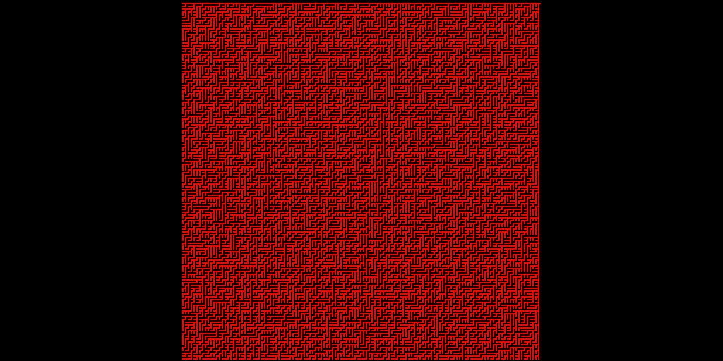
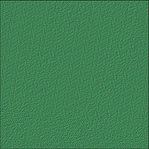
}I added some checks so that we can modify the parameters in realtime and see the effects. If you put it all together, you’ll see a result like this:
If you found this post interesting, join my mailing list to hear about future posts. The complete project is available here on Github. If you find compute shaders interesting, check out this intro to compute shaders or this compute shader workshop, both by Arsiliath. If you’d like to learn more about maze generation algorithms, check out the book Mazes for Programmers by Jamis Buck.