Simple Mesh Voxelization in Unity
bronson
- posted on
- 5 Comments
In this article, I explore a naive approach to mesh voxelization in Unity. Mesh voxelization is a helpful tool to determine mesh connectivity and volume. We can use this information to create pathfinding grids, heat diffusion maps, global illumination, simplified physics representations and more.
What is Voxelization?
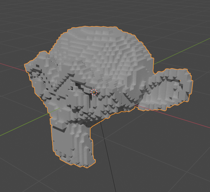
Voxelization is the process of converting something into its voxel representation. What’s a voxel representation? Basically, instead of representing a mesh as a series of connected triangles, imagine a mesh as a collection of equally-sized blocks on a 3d grid. This comparison should illustrate what I mean:
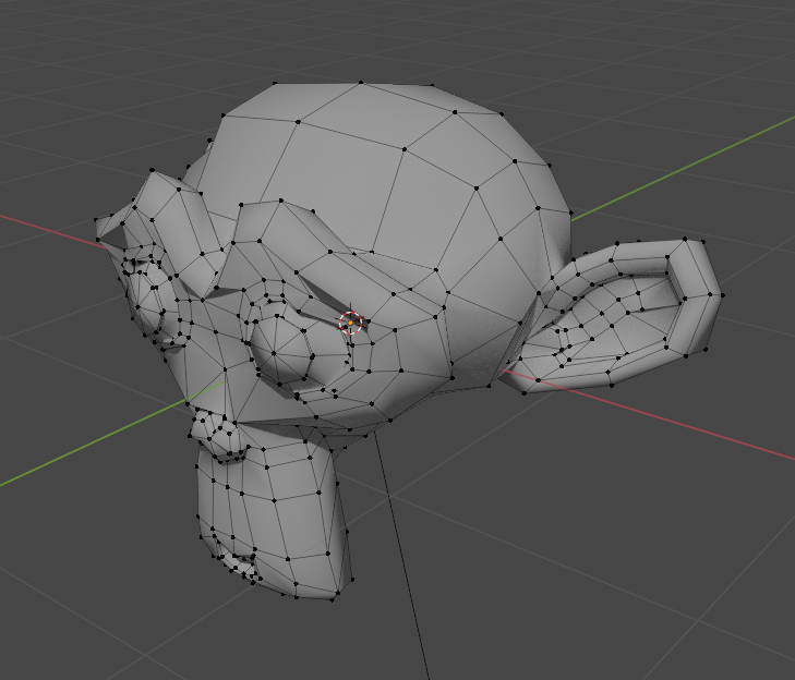
To put it bluntly, if you forced a mesh to conform to a 3d grid, that’s voxelization.
How can we use a voxelized mesh?
Most of the advantages that a voxelized mesh has over a triangle mesh come down to its ability to hold information about volume and connectivity. For example, some developers have used voxelized meshes to implement automatic vertex skinning. I’ll share some resources about this later in the article. When calculating automatic skinning weights, a voxelized mesh represents the distance between a bone and vertex more accurately than the euclidean distance by only moving through the connected voxels to reach the destination.
Unity’s NavMesh system also uses voxelization. The first step of the NavMesh baking process is to voxelize the scene. This step transforms all the arbitrary geometry into a single connected representation.
These are just a couple of uses for voxelization, but there are more. I hope to explore some of these systems in the future, but it’s enough to understand what voxelization is for this article.
How do we voxelize a mesh?
There are several techniques to voxelize a mesh. If you search online, you’ll find plenty of white papers on the subject. However, for this article, we’ll do it in the most straightforward way I could imagine. My process is single-threaded and runs on the CPU. The voxel data structure is naive as well. However, the algorithm’s simplicity provides a good starting point when entering the world of voxelization. It’ll also serve as a worst-case benchmark when exploring more optimized methods in the future. So let’s get into it.
To start, we’ll create the voxelized mesh representation. We need two things: the voxel size and a list of solid grid points. A voxel grid is a regular grid, which means it’s composed of identically sized cubes equidistant apart. So for the voxel size, we could store the length of one side of a cube and extrapolate from there. However, it’s also helpful to know the half-length, so let’s hold that instead and double it when necessary. As for the grid points, let’s keep a list of Vector3Int values. If a point is present in the grid, we add it to the list. It doesn’t get more naive than this.
public class VoxelizedMesh : MonoBehaviour
{
    public List<Vector3Int> gridPoints = new List<Vector3Int>();
    public float HalfSize = 0.1f;
}
Before we continue, let’s add a helper method to convert from a grid point to a position. Given a point in the grid, we calculate its position by multiplying x, y and z by the size of a grid cell. We also need to know where the grid starts relative to the object’s origin. We’ll call this the local origin of the grid. Finally, I chose to nudge everything over so that the center of the first grid cell lies inside the bounds rather than on the edge of the bounds. Here’s our updated class:
public class VoxelizedMesh : MonoBehaviour
{
    public List<Vector3Int> GridPoints = new List<Vector3Int>();
    public float HalfSize = 0.1f;
    public Vector3 LocalOrigin;

    public Vector3 PointToPosition(Vector3Int point)
    {
        float size = HalfSize * 2f;
        Vector3 pos = new Vector3(HalfSize + point.x * size, HalfSize + point.y * size, HalfSize + point.z * size);
        return LocalOrigin + transform.TransformPoint(pos);
    }
}
Now let’s fill in the data. The simple approach is:
- Add a
MeshColliderto our object - Use the
MeshColliderbounds to define the bounds of the voxel grid. - For every point in the voxel grid, check if it intersects with the
MeshCollider. If it does, add it to the list.
That’s all there is to it. Initially, I hoped to multithread the algorithm, but I want to take advantage of Unity’s Physics API, which runs exclusively on the main thread. In the future, we’ll write a custom method to check the intersection between a voxel and a triangle which will allow us to multithread our code using Jobs or the GPU. Anyway, here’s the whole function:
public static void VoxelizeMesh(MeshFilter meshFilter)
{
    if (!meshFilter.TryGetComponent(out MeshCollider meshCollider))
    {
        meshCollider = meshFilter.gameObject.AddComponent<MeshCollider>();
    }

    if (!meshFilter.TryGetComponent(out VoxelizedMesh voxelizedMesh))
    {
        voxelizedMesh = meshFilter.gameObject.AddComponent<VoxelizedMesh>();
    }

    Bounds bounds = meshCollider.bounds;
    Vector3 minExtents = bounds.center - bounds.extents;
    float halfSize = voxelizedMesh.HalfSize;
    Vector3 count = bounds.extents / halfSize;

    int xMax = Mathf.CeilToInt(count.x);
    int yMax = Mathf.CeilToInt(count.y);
    int zMax = Mathf.CeilToInt(count.z);

    voxelizedMesh.GridPoints.Clear();
    voxelizedMesh.LocalOrigin = voxelizedMesh.transform.InverseTransformPoint(minExtents);

    for (int x = 0; x < xMax; ++x)
    {
        for (int z = 0; z < zMax; ++z)
        {
            for (int y = 0; y < yMax; ++y)
            {
                Vector3 pos = voxelizedMesh.PointToPosition(new Vector3Int(x, y, z));
                if (Physics.CheckBox(pos, new Vector3(halfSize, halfSize, halfSize)))
                {
                    voxelizedMesh.GridPoints.Add(new Vector3Int(x, y, z));
                }
            }
        }
    }
}
Let’s break it down one piece at a time. First of all, some code to ensure the object has a MeshCollider and a VoxelizedMesh component. Nothing surprising here:
    if (!meshFilter.TryGetComponent(out MeshCollider meshCollider))
    {
        meshCollider = meshFilter.gameObject.AddComponent<MeshCollider>();
    }

    if (!meshFilter.TryGetComponent(out VoxelizedMesh voxelizedMesh))
    {
        voxelizedMesh = meshFilter.gameObject.AddComponent<VoxelizedMesh>();
    }
Next, we’re going to establish the bounds of the grid and find our starting point, that is, the position of point (0, 0, 0). We’ll start with the Bounds of our MeshCollider component. The Bounds is a box that encompasses the entire mesh. From there, we can calculate the minimum point of the box, which is the bottom-front-center point. Next, calculate how many voxels we can fit in each dimension, rounding up to the nearest whole number. Finally, we’ll store the minimum point, minExtents, the LocalOrigin of our voxel grid. If you recall, the LocalOrigin allows us to convert our grid points to a world-space position.
Bounds bounds = meshCollider.bounds;
Vector3 minExtents = bounds.center - bounds.extents;
float halfSize = voxelizedMesh.HalfSize;
Vector3 count = bounds.extents / halfSize;

int xMax = Mathf.CeilToInt(count.x);
int yMax = Mathf.CeilToInt(count.y);
int zMax = Mathf.CeilToInt(count.z);

voxelizedMesh.GridPoints.Clear();
voxelizedMesh.LocalOrigin = voxelizedMesh.transform.InverseTransformPoint(minExtents);
Now, all that’s left to do is fill it all in. So, we iterate through each position in the grid and check if it intersects with the collider.
for (int x = 0; x < xGridSize; ++x)
{
    for (int z = 0; z < zGridSize; ++z)
    {
        for (int y = 0; y < yGridSize; ++y)
        {
            Vector3 pos = voxelizedMesh.PointToPosition(new Vector3Int(x, y, z));
            if (Physics.CheckBox(pos, new Vector3(halfSize, halfSize, halfSize)))
            {
                voxelizedMesh.GridPoints.Add(new Vector3Int(x, y, z));
            }
        }
    }
}
Finally, before we finish, let’s write a custom editor to display our voxel representation. To do this, make a new class that inherits from Editor and give it the CustomEditor attribute for typeof(VoxelizedMesh). Now, we can override OnSceneGUI and draw whatever we want. Iterate through all the GridPoints, convert each one to a position, and draw it. I decided to draw a wireframe cube to represent each solid voxel and one more to display the MeshCollider bounds. By the way, make sure Gizmos are enabled or else OnSceneGUI won’t draw.
[CustomEditor(typeof(VoxelizedMesh))]
public class VoxelizedMeshEditor : Editor
{
    void OnSceneGUI()
    {
        VoxelizedMesh voxelizedMesh = target as VoxelizedMesh;

        Handles.color = Color.green;
        float size = voxelizedMesh.HalfSize * 2f;

        foreach (Vector3Int gridPoint in voxelizedMesh.GridPoints)
        {
            Vector3 worldPos = voxelizedMesh.PointToPosition(gridPoint);
            Handles.DrawWireCube(worldPos, new Vector3(size, size, size));
        }

        Handles.color = Color.red;
        if (voxelizedMesh.TryGetComponent(out MeshCollider meshCollider))
        {
            Bounds bounds = meshCollider.bounds;
            Handles.DrawWireCube(bounds.center, bounds.extents * 2);
        }
    }
}
You should end up with something like this:
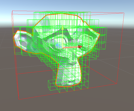
So this wraps up our naive implementation to mesh voxelization. It’s certainly not perfect, but it’s a start. In the future, I’ll show how we can multithread the process to make it much faster.
Check out the whole project on Github. If you’re interested in ways to use your new voxelized model, read this article from David Rosen on automatic skinning. Here’s a Blender add-on that uses a similar approach. This library uses voxelization to create pathfinding information. If you like my blog, join my mailing list to be notified when I post a new article.
Bit
Is this possible to convert to a smooth voxel format? Very interesting concept to do this directly in unity thank you for sharing 🙂
bronson
I believe so. It’s a matter of how the data is displayed. The voxelization data represents the volume of the object, but not the method used to draw it. I used one cube per-voxel, but that’s an arbitrary choice.
To actually do it, I would suggest something like the Marching Cubes or Sphere Tracing algorithms. These allow you to render implicit surfaces (so no triangles needed) and by manipulating the density and threshold values you can create smoother looking surfaces.
I hope that helps!
JL
Hey Bronson!
I can’t thank you enough for this detailed article. It actually gave me a lot of insight on the whole voxelization process as a whole. My programming days are long behind me, but I was still surprised to be able to follow along in some parts, thanks to your detailed explanations.
I’m currently doing a ton of exploration on the topic of voxelization and I’ve faced a bit of a problem recently. All to say, I was just wondering if you wouldn’t mind me I e-mailing you regarding the problem? If anything, your comments/insights would be greatly appreciated. If I had to summarize the problem in a few words, it would be about the act of properly voxelizing an already voxel-type mesh (if that makes sense?). That’s the best way I can sum it up.
Thanks a ton!
RAHUL LEKH TANDON
Mesh colliders are said to slow the CPU. your experience?
bronson
The more complex a collider is the more time it takes to calculate, so it’s a balance between the ease-of-use and accuracy of a mesh collider versus the performance of other colliders. Measuring the difference could be an interesting topic for a future post.