GPU Mesh Voxelizer Part 2: Triangle / Voxel intersection
bronson
- posted on
- No Comment
In this article, we’ll continue porting our mesh voxelizer to the GPU. If you haven’t read them already, you can read the first two parts here and here. We’ll build off the bones we created in the last article and start implementing the Separating Axis Theorem to test intersections between voxels and triangles.
Triangle / Voxel intersection with Separating Axis Theorem
To check if a triangle from the mesh intersects with a given voxel, we’ll use the Separating Axis Theorem (SAT). I’ve linked some resources at the end if you’d like a more in-depth explanation of the algorithm, but I’ll provide a simplified description here. Essentially, we look at the two shapes straight-on from a handful of specific angles. If any one of those angles shows the two shapes aren’t overlapping, we know the shapes aren’t intersecting. Here’s a simple example using two boxes and examining three axes:
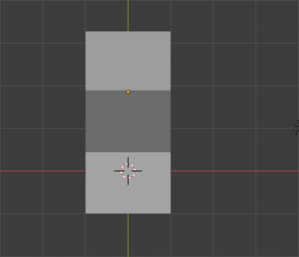
Top View 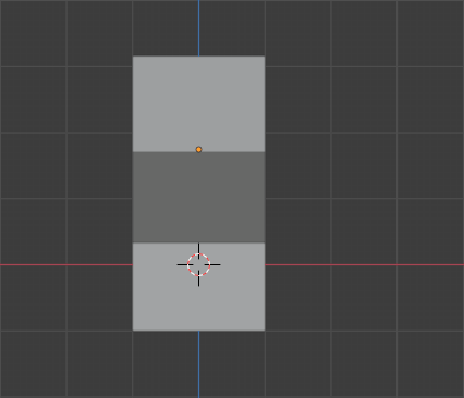
Front View 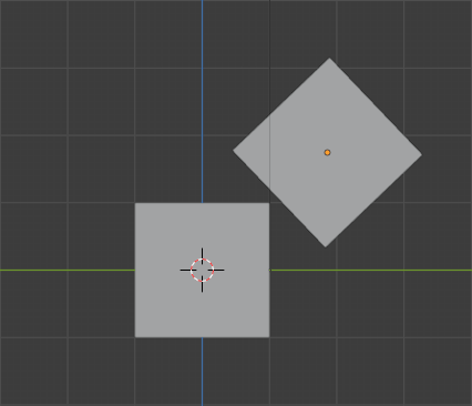
Right View
By the way, to do this properly, we need to check more than three axes. In our case, we’re testing triangles against Axis-Aligned Bounding Boxes (AABBs). So, the algorithm states that we need to test against 13 different axes:
- The three positive face normals of the AABB.
- The face normal of the triangle.
- The cross product between each (positive) AABB face normal with each triangle edge normal. That’s three normals each, so a total of nine.
After calculating each axis, we then project both shapes onto the stated axis, reducing each shape to a single line. Then we check if these lines overlap. As soon as we find an axis onto which the shapes don’t overlap, we can exit the algorithm knowing that the shapes aren’t intersecting. Here’s a crude drawing of projecting both shapes onto a single axis and confirming the overlap:
So let’s write the Compute Shader. We’ll tackle the intersection between a triangle and an AABB onto a single axis first. This function will project both shapes onto one axis and check if they overlap. Here’s the complete function:
bool IntersectsTriangleAabbSat(float3 v0, float3 v1, float3 v2, float3 aabbExtents, float3 axis)
{
    float p0 = dot(v0, axis);
    float p1 = dot(v1, axis);
    float p2 = dot(v2, axis);

    float r = aabbExtents.x * abs(dot(float3(1, 0, 0), axis)) +
        aabbExtents.y * abs(dot(float3(0, 1, 0), axis)) +
        aabbExtents.z * abs(dot(float3(0, 0, 1), axis));

    float maxP = max(p0, max(p1, p2));
    float minP = min(p0, min(p1, p2));

    return !(max(-maxP, minP) > r);
}
Step one is projecting each of the triangle vertices onto the axis using dot. So p0, p1 and p2 are the vertices v0, v1, and v2 after being projected. The next part will take more time to unpack, but I’ll do my best to explain:
- Assume the AABB is at the origin.
- Project the face normal onto the provided axis. The result is a number between -1 and 1.
- Take the absolute value to convert the result to a value between 0 and 1. This number essentially represents how aligned the face normal and the axis are.
- Multiply that value by the AABB extent. Once we do that for each face and sum all the values, we have a single value,
r. This value is the length of the AABB projection onto a single axis. - Find the minimum and maximum points (
minPandmaxP) of the projected triangle to create a line fromminPtomaxP. - Check if the line 0 to
roverlaps with the lineminPtomaxP.
If you’re still struggling to understand, I recommend drawing out all the steps.
The next part is straightforward; we call that function 13 times with each of the axes mentioned above. As soon as one of the axes doesn’t intersect, we return false. Here’s the code:
bool IntersectsTriangleAabb(Triangle tri, AABB aabb)
{
    tri.a -= aabb.center;
    tri.b -= aabb.center;
    tri.c -= aabb.center;

    float3 ab = normalize(tri.b - tri.a);
    float3 bc = normalize(tri.c - tri.b);
    float3 ca = normalize(tri.a - tri.c);

    //Cross ab, bc, and ca with (1, 0, 0)
    float3 a00 = float3(0.0, -ab.z, ab.y);
    float3 a01 = float3(0.0, -bc.z, bc.y);
    float3 a02 = float3(0.0, -ca.z, ca.y);

    //Cross ab, bc, and ca with (0, 1, 0)
    float3 a10 = float3(ab.z, 0.0, -ab.x);
    float3 a11 = float3(bc.z, 0.0, -bc.x);
    float3 a12 = float3(ca.z, 0.0, -ca.x);

    //Cross ab, bc, and ca with (0, 0, 1)
    float3 a20 = float3(-ab.y, ab.x, 0.0);
    float3 a21 = float3(-bc.y, bc.x, 0.0);
    float3 a22 = float3(-ca.y, ca.x, 0.0);

    if (
        !IntersectsTriangleAabbSat(tri.a, tri.b, tri.c, aabb.extents, a00) ||
        !IntersectsTriangleAabbSat(tri.a, tri.b, tri.c, aabb.extents, a01) ||
        !IntersectsTriangleAabbSat(tri.a, tri.b, tri.c, aabb.extents, a02) ||
        !IntersectsTriangleAabbSat(tri.a, tri.b, tri.c, aabb.extents, a10) ||
        !IntersectsTriangleAabbSat(tri.a, tri.b, tri.c, aabb.extents, a11) ||
        !IntersectsTriangleAabbSat(tri.a, tri.b, tri.c, aabb.extents, a12) ||
        !IntersectsTriangleAabbSat(tri.a, tri.b, tri.c, aabb.extents, a20) ||
        !IntersectsTriangleAabbSat(tri.a, tri.b, tri.c, aabb.extents, a21) ||
        !IntersectsTriangleAabbSat(tri.a, tri.b, tri.c, aabb.extents, a22) ||
        !IntersectsTriangleAabbSat(tri.a, tri.b, tri.c, aabb.extents, float3(1, 0, 0)) ||
        !IntersectsTriangleAabbSat(tri.a, tri.b, tri.c, aabb.extents, float3(0, 1, 0)) ||
        !IntersectsTriangleAabbSat(tri.a, tri.b, tri.c, aabb.extents, float3(0, 0, 1)) ||
        !IntersectsTriangleAabbSat(tri.a, tri.b, tri.c, aabb.extents, cross(ab, bc))
    )
    {
        return false;
    }

    return true;
}
I’ll go over it briefly:
- We translate the triangle by the AABB’s position. Doing this moves the origin to the center of the AABB for the calculations that follow.
- We calculate the three triangle edge normals.
- We cross each of the edge normals with each of the AABB axes. You probably noticed I didn’t use the cross-product function. Since the AABB is axis-aligned, we know the three axes will always be (1, 0, 0), (0, 1, 0) and (0, 0, 1). So, as an optimization, I hardcoded the results of the cross-products.
- Check the intersection with those 9 axes, the 3 AABB face normals and the triangle face normal. If any of them fail, return false.
To wrap this up, we’ll go over the main kernel method.
[numthreads(4,4,4)]
void VoxelizeMesh(uint3 id : SV_DispatchThreadID)
{
    if (id.x >= _GridWidth || id.y >= _GridHeight || id.z >= _GridDepth) return;

    const float cellSize = _CellHalfSize * 2.0;

    const float3 centerPos = float3(
	id.x * cellSize + _CellHalfSize + _BoundsMin.x,
        id.y * cellSize + _CellHalfSize + _BoundsMin.y,
        id.z * cellSize + _CellHalfSize + _BoundsMin.z);

    AABB aabb;
    aabb.center = centerPos.xyz;
    aabb.extents = float3(_CellHalfSize, _CellHalfSize, _CellHalfSize);

    bool intersects = false;
    for (int i = 0; i < _TriangleCount; i += 3)
    {
        Triangle tri;
        tri.a = _MeshVertices[_MeshTriangleIndices[i]];
        tri.b = _MeshVertices[_MeshTriangleIndices[i + 1]];
        tri.c = _MeshVertices[_MeshTriangleIndices[i + 2]];
        intersects = IntersectsTriangleAabb(tri, aabb);

        if (intersects)
            break;
    }

    float w = intersects ? 1.0 : 0.0;
    _VoxelGridPoints[id.x + _GridWidth * (id.y + _GridHeight * id.z)] = float4(
        _BoundsMin.x + id.x * cellSize,
        _BoundsMin.y + id.y * cellSize,
        _BoundsMin.z + id.z * cellSize, w);
}
This code should look familiar if you followed the previous tutorial. We run this function once per voxel. For each voxel, we determine the position of its AABB. Then, we iterate through every triangle of the mesh and check if it intersects with the AABB. I decided to use the w component of the voxel point to store the result of the intersection check. Doing so allows us to keep everything packed into a single float4, but we’ll have to handle it in the drawing shader.
Drawing the Voxel Grid
The rendering shader is nearly identical to the previous tutorial. The difference is we’ll draw colliding voxels in a different colour so we can visualize the results of our voxelization. Here’s the updated vertex function:
v2f vert(uint vertex_id : SV_VertexID, uint instance_id : SV_InstanceID)
{
    v2f o;
    float4 pos = _VoxelGridPoints[instance_id];
    o.color = lerp(_Color, _CollisionColor, pos.w);
    o.position = UnityWorldToClipPos(mul(_LocalToWorldMatrix, float4(pos.xyz, 1.0)));
    o.size = 5;
    return o;
}
Since we set the position’s w component to 1 on intersection and 0 otherwise, we lerp between the base colour and the collision colour using w. If you want to see the entire shader, including all the boilerplate, check the file Voxel.shader in the complete project on GitHub that’s linked at the end.
Let’s take a look at the VoxelizedMesh.cs script and wrap this up.
Voxelized Mesh script
Functionally, the VoxelizedMesh script hasn’t changed much. The main difference is that we now pass the vertices and triangle indices into the compute shader. However, I took this opportunity to switch from using OnRenderObject and DrawProceduralNow to DrawProceduralIndirect inside Update. Also, previously we allocated a lot of garbage by creating a large new array every frame, so I cleaned that up. Doing so results in a massive performance boost. In contrast, before, I dropped frames drawing 2 million points, now I can draw over 4 million (without checking for triangle intersections). So let’s convert from DrawProceduralNow to DrawProceduralIndirect.
Draw Procedural Indirect
The difference between DrawProceduralNow and DrawProceduralIndirect is that we supply the vertex count and instance count via a compute buffer rather than a function argument. We also pass the mesh bounds for culling. Here’s the new Update function that replaces the old OnRenderObject function:
void Update()
{
    VoxelizeMeshWithGPU();

    if (_drawDebug)
    {
        _gridPointMaterial.SetMatrix(LocalToWorldMatrix, transform.localToWorldMatrix);
        _gridPointMaterial.SetVector(BoundsMin, new Vector4(_boundsMin.x, _boundsMin.y, _boundsMin.z, 0.0f));
        _gridPointMaterial.SetBuffer(VoxelGridPoints, _voxelPointsBuffer);
        _pointsArgsBuffer.SetData(new[] {1, _gridPointCount, 0, 0, 0});
        Graphics.DrawProceduralIndirect(_gridPointMaterial, _meshCollider.bounds, MeshTopology.Points,
            _pointsArgsBuffer);
    }
}
The _pointsArgsBuffer is an IndirectArgumentsBuffer that holds 5 integer values:
- Vertex count per instance
- Instance count
- Start vertex location
- Start instance location
- A reserved value that’s always 0
In our case, points always have a single vertex per instance, and each grid point is an instance. Everything else is 0. Another difference from the previous version is that we no longer call SetPass on the material; the rendering pipeline will do that for us. I create the _pointsArgsBuffer in OnEnable like this:
void OnEnable()
{
    _pointsArgsBuffer = new ComputeBuffer(1, 5 * sizeof(uint), ComputeBufferType.IndirectArguments);
}
It’s important to note the extra constructor argument to specify the type ComputeBufferType.IndirectArguments.
Last but not least, there’s the VoxelizeMeshWithGPU method. The function has grown quite long thanks to the optimizations. At its core, it sets up the compute buffers and asks the GPU to work. However, to avoid allocating unnecessary garbage, we check if we can reuse the existing arrays and compute buffers before creating new ones. Here’s the entire function:
void VoxelizeMeshWithGPU()
{
    Bounds bounds = _meshCollider.bounds;
    _boundsMin = transform.InverseTransformPoint(bounds.min);

    Vector3 voxelCount = bounds.extents / _halfSize;
    int xGridSize = Mathf.CeilToInt(voxelCount.x);
    int yGridSize = Mathf.CeilToInt(voxelCount.y);
    int zGridSize = Mathf.CeilToInt(voxelCount.z);

    bool resizeVoxelPointsBuffer = false;
    if (_gridPoints == null || _gridPoints.Length != xGridSize * yGridSize * zGridSize ||
        _voxelPointsBuffer == null)
    {
        _gridPoints = new Vector4[xGridSize * yGridSize * zGridSize];
        resizeVoxelPointsBuffer = true;
    }

    if (resizeVoxelPointsBuffer || _voxelPointsBuffer == null || !_voxelPointsBuffer.IsValid())
    {
        _voxelPointsBuffer?.Dispose();
        _voxelPointsBuffer = new ComputeBuffer(xGridSize * yGridSize * zGridSize, 4 * sizeof(float));
    }

    if (resizeVoxelPointsBuffer)
    {
        _voxelPointsBuffer.SetData(_gridPoints);
    }

    if (_meshVerticesBuffer == null || !_meshVerticesBuffer.IsValid())
    {
        _meshVerticesBuffer?.Dispose();

        var sharedMesh = _meshFilter.sharedMesh;
        _meshVerticesBuffer = new ComputeBuffer(sharedMesh.vertexCount, 3 * sizeof(float));
        _meshVerticesBuffer.SetData(sharedMesh.vertices);
    }

    if (_meshTrianglesBuffer == null || !_meshTrianglesBuffer.IsValid())
    {
        _meshTrianglesBuffer?.Dispose();

        var sharedMesh = _meshFilter.sharedMesh;
        _meshTrianglesBuffer = new ComputeBuffer(sharedMesh.triangles.Length, sizeof(int));
        _meshTrianglesBuffer.SetData(sharedMesh.triangles);
    }

    var voxelizeKernel = _voxelizeComputeShader.FindKernel("VoxelizeMesh");
    _voxelizeComputeShader.SetInt("_GridWidth", xGridSize);
    _voxelizeComputeShader.SetInt("_GridHeight", yGridSize);
    _voxelizeComputeShader.SetInt("_GridDepth", zGridSize);

    _voxelizeComputeShader.SetFloat("_CellHalfSize", _halfSize);

    _voxelizeComputeShader.SetBuffer(voxelizeKernel, VoxelGridPoints, _voxelPointsBuffer);
    _voxelizeComputeShader.SetBuffer(voxelizeKernel, "_MeshVertices", _meshVerticesBuffer);
    _voxelizeComputeShader.SetBuffer(voxelizeKernel, "_MeshTriangleIndices", _meshTrianglesBuffer);
    _voxelizeComputeShader.SetInt("_TriangleCount", _meshFilter.sharedMesh.triangles.Length);

    _voxelizeComputeShader.SetVector(BoundsMin, _boundsMin);

    _voxelizeComputeShader.GetKernelThreadGroupSizes(voxelizeKernel, out uint xGroupSize, out uint yGroupSize,
        out uint zGroupSize);

    _voxelizeComputeShader.Dispatch(voxelizeKernel,
        Mathf.CeilToInt(xGridSize / (float) xGroupSize),
        Mathf.CeilToInt(yGridSize / (float) yGroupSize),
        Mathf.CeilToInt(zGridSize / (float) zGroupSize));
    _gridPointCount = _voxelPointsBuffer.count;
}
One last bit, don’t forget to Dispose of your compute buffers. I do that in OnDisable like so:
void OnDisable()
{
    _pointsArgsBuffer?.Dispose();
    _voxelPointsBuffer?.Dispose();
    _meshTrianglesBuffer?.Dispose();
    _meshVerticesBuffer?.Dispose();
}
Doing this will invalidate the buffers, but they won’t be null. You can check if a buffer is invalid using IsValid() as shown in the method above and recreate them.
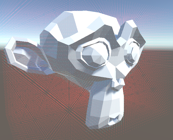
So, by the end of all this, you’ll be able to detect which voxels are solid and which aren’t. The following screenshot shows the active voxels. Each blue dot is the corner of a solid voxel in a grid of about 600k voxels.
If you want to dive into the code, I suggest you explore the complete project on GitHub. If you appreciate this article, join my mailing list, and I’ll email you when part 3 is released.